
Direct current
HVDC transmission explained: the cable, the converter station and why DC wins
Alternating current built the grid. For long routes, and for almost anything laid on the seabed, the physics favours direct current: HVDC transmission.
AC or DC: at what distance does direct current win?
Move the slider to set the length of a new link, then switch between an overhead line and a cable. AC starts cheaper because it needs no converter stations; DC loses less along the way. Where the two cost curves cross is the break-even distance, and for cables it arrives far sooner than for lines in the open air.
At 400 km on an overhead route, AC costs less.
- Break-even
- 650km
- AC total
- –
- DC total
- –
On this page
Between Bicker Fen in Lincolnshire and Revsing in South Jutland, 765 km of cable carries up to 1,400 MW at ±525 kV. Viking Link went into commercial operation on 29 December 2023, and no engineer would have considered building it with alternating current. At that length, under the North Sea, an AC cable would spend its entire capacity charging itself. What is HVDC, then? High-voltage direct current is the technology Europe uses when a route is too long, too wet or too awkward for the AC grid that carries almost everything else.
What is HVDC doing in a grid that already runs well on AC? The short answer: the jobs AC cannot do. The rest of this page follows the current from one end of an HVDC link to the other. It starts with the physics, then the two families of converter, what sits inside a converter station, the HVDC cable itself, and finally where the links run and what still holds them back.
Why HVDC transmission wins over distance and under the sea
Every high-voltage cable is built the same way at its core: a copper or aluminium conductor, a thick layer of insulation, and a metallic sheath held at earth potential. Two conductors separated by an insulator make a capacitor. In a cable that capacitor is stretched out over the whole route, and it is a large one, because the conductor and the sheath sit only centimetres apart.
With alternating current the voltage on that conductor reverses direction a hundred times a second on Europe’s 50 Hz grid. Each reversal means the whole length of cable has to be charged up to the new polarity, and the current that does the charging flows through the conductor whether or not any power is being delivered at the far end. Engineers call it charging current. It grows in proportion to the length of the cable. The conductor, though, has a fixed rating: only so much current can flow before the heat damages the insulation. As the cable gets longer, the charging current takes a bigger share of that rating, until at some length there is no room left for useful power at all.
Onshore, an AC cable can be helped along with reactors placed along the route that absorb the charging current. Offshore that is rarely possible. National Grid’s technical factsheet on HVDC puts it plainly: reactive compensation cannot be installed mid-route under the sea, long AC cable sections are very difficult to joint offshore, and so AC transmission distances at sea are restricted.
Overhead lines suffer from the same effect in a much milder form. Their conductors hang metres apart in air, so their capacitance per kilometre is far lower and an AC line can run for hundreds of kilometres. What limits them over very long distances is the reactive power flowing back and forth along the line, which ENTSO-E identifies as the factor that caps AC transmission distance and adds to its cost.
Direct current removes the problem at the root. A DC cable is charged once, when the link is energised, and then carries only the current that is actually delivering power. A DC circuit also needs two conductors where a three-phase AC circuit needs three, and it can join two AC grids that are not synchronised with each other, such as Great Britain and continental Europe.
Distance is not the only reason to choose DC. Some links are built inside a single synchronous grid purely for control: ENTSO-E cites the Western HVDC Link between Scotland and north Wales as a good example of an embedded link, and ALEGrO between Belgium and Germany, only 90 km long and fully underground, does the same job across a border inside the continental grid. Operators can set the flow on an HVDC transmission line precisely, while power on an AC line spreads itself across the network according to the physics of every parallel path.
The price is paid at the ends. Each HVDC link needs a converter station at both terminals, and those stations are expensive. HVDC transmission therefore loses on short routes and wins on long ones, with a break-even point somewhere in between. ENTSO-E’s paper HVDC Links in System Operations gives break-even distances in the order of 500–800 km for overhead lines and 40–150 km for cable connections, depending on the voltage, and stresses that the figures are highly project-dependent. For a route that is both long and subsea, the answer rarely needs a calculator. The comparison below lets you move the distance yourself and watch where the two cost curves cross.
LCC and VSC: two ways to build an HVDC converter station
The first commercial HVDC link in the world was built by ASEA in 1954 to the island of Gotland: 20 MW at 100 kV over 96 km, according to Hitachi Energy’s HVDC heritage timeline. Its converters used mercury-arc valves. Thyristor valves, which replaced them, were first used in a commercial HVDC project in 1970, and the thyristor-based line-commutated converter (LCC) is still the technology behind the highest-rated links on earth.
An LCC depends on the AC network it is connected to. Its thyristors can be switched on by a control pulse but only switch off when the AC voltage around them reverses, which is where the name comes from. That dependence has consequences. National Grid’s factsheet lists them: the converter absorbs reactive power equal to about half the active power it transmits, generates harmonics that need large AC filters, can suffer commutation failure when a fault disturbs the AC voltage, and has to reverse the polarity of the DC voltage to reverse the direction of power flow. The last point matters for cables, as the next sections show.
The voltage source converter (VSC) arrived in 1997. ENTSO-E dates the first VSC-HVDC system to that year, at ±10 kV and 3 MW; Hitachi Energy identifies it as the test connection between Hällsjön and Grängesberg in central Sweden. VSC valves are built from insulated gate bipolar transistors (IGBTs), which can be switched off as well as on. The converter no longer needs a strong AC network to work, it controls active and reactive power independently, it can reverse power flow without reversing voltage, and it can energise a network that has no power of its own. That last property is what makes it the default for connecting offshore wind farms, the subject of the project’s first demonstration.
Early VSC designs switched between two or three voltage levels. The current generation, the modular multilevel converter (MMC), stacks a large number of small submodules to build up a smooth waveform step by step. ENTSO-E notes that the modular concept reduces losses and improves harmonic performance.
The shift in Europe is clear from the links themselves. IFA, opened across the Channel in 1986, and NorNed, 580 km between Norway and the Netherlands from 2008, are LCC schemes. Of the 16 HVDC links in this directory that entered service from 2018 onwards, 14 use VSC. The one LCC scheme among them is the Western HVDC Link, 422 km from Hunterston on the Clyde to Deeside, and for one more the technology is not recorded. For a new European interconnector, VSC is now the default.
What is inside an HVDC converter station
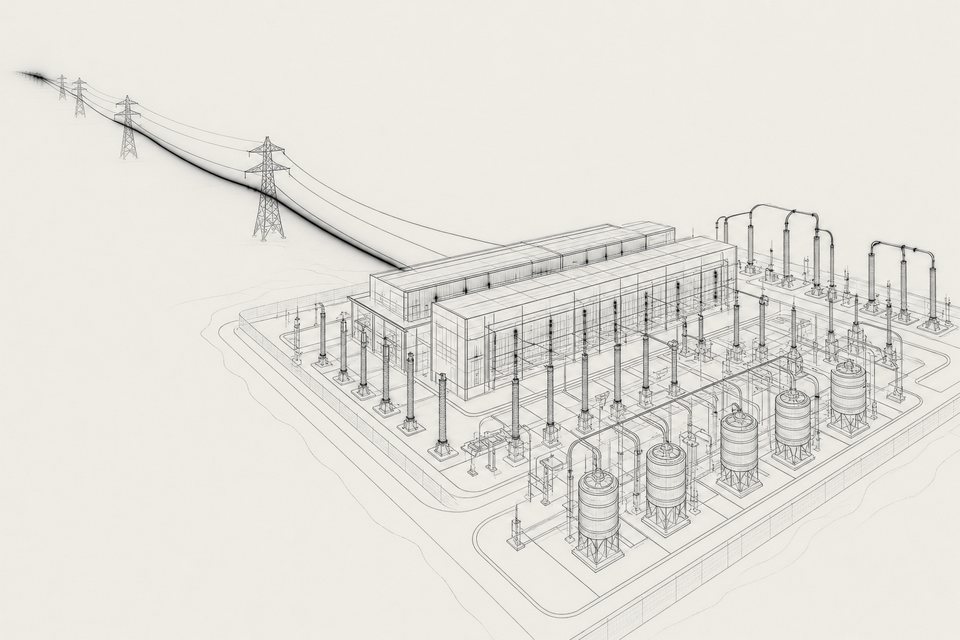
A converter station is mostly buildings. The valves, the heart of the station, sit in tall valve halls with controlled climate, because DC equipment attracts dust and pollution from the air. Around them stand the converter transformers, which match the AC grid voltage to the converter; on LCC stations these need a special design, while VSC stations can often use conventional transformers. An LCC station adds banks of switched AC harmonic filters and reactive compensation, and a smoothing reactor on the DC side. Add a DC switchyard, cooling plant for the valves, auxiliary supplies and a control building, and the site becomes substantial.
National Grid’s factsheet gives an average footprint of about 200 m by 120 m for an LCC station, with valve halls around 22 m high, and notes that the filters and compensation can account for more than half of that area. A VSC station of similar rating needs roughly 120 m by 60 m, around 40% of the space, because it has no reactive compensation to house. Almost all of its equipment is indoors.
Size varies with rating. On the Caithness–Moray link in northern Scotland the station at Blackhillock is rated 1,200 MW and the one at Spittal 800 MW, both at 320 kV. Offshore, the converter sits on a platform the size of a large building, which is one reason every tonne and every square metre saved by VSC design matters.
Losses are the running cost. The factsheet puts them at 0.7–0.8% of transmitted power per LCC converter station and about 1% per VSC station, or about 2% for a complete VSC link with a station at each end. Those figures date from 2013, before modular multilevel converters were widespread, and the modular design has since brought VSC losses down. Even so, the arithmetic is worth doing once: on a 1,400 MW link, a single percentage point is 14 MW, lost as heat every hour the link runs at full power.
The HVDC cable: mass-impregnated paper and XLPE
Two insulation technologies carry nearly all HVDC cable routes in Europe.
Mass-impregnated (MI) cable is the older one. Layers of kraft paper are wound around the conductor until the insulation is thick enough, the core is dried under vacuum, and a viscous oil is worked into the paper. A newer variant laminates thin layers of polypropylene between the paper so the cable can run hotter and carry more current. National Grid gave MI cables as available up to 600 kV, the voltage of the Western HVDC Link. MI is also still chosen for some of the newest routes: Prysmian’s cable for Viking Link, at ±525 kV, is paper-insulated.
Cross-linked polyethylene (XLPE) is extruded over the conductor as a solid plastic layer, the same method used for most AC cables. It is lighter, simpler to joint and needs no oil. Its weakness is voltage reversal: XLPE is unsuitable for LCC links that reverse polarity to change the direction of flow, so extruded HVDC cable has grown up alongside VSC. The long-standing ceiling was 320 kV, the voltage of many VSC interconnectors in service today. In May 2020 NKT won the first commercial order for a 525 kV XLPE HVDC cable system, for the SuedOstLink corridor in Germany, and the 525 kV underground cables of SuedLink, two 2 GW circuits totalling about 700 km, are due to connect in 2028.
Both types need steel armouring for the seabed, and both are laid from specialist ships that can joint cable at sea during a few days of calm weather. Depth is its own challenge: the SAPEI cable to Sardinia reaches 1,600 m, and the Tyrrhenian Link, now under construction, has set a laying record of 2,150 m. The practical side of this, from route surveys to burial and repair, is covered in the guide to subsea power cables.
A damaged HVDC cable is out of service for a long time. National Grid warned that a submarine cable fault can take a link out for up to six months. Estlink 2 between Finland and Estonia was damaged by a dragged anchor on 25 December 2024 and returned to full operation in June 2025.
From point-to-point to multi-terminal HVDC transmission
Almost every HVDC link built so far has exactly two ends. Power goes in at one converter and comes out at the other, and the operator sets how much. That simplicity is part of the appeal, but it also means each link is an island of DC in an AC sea. Plugging a third converter into an existing link, the way a new substation is added to an AC network, is not straightforward.
One Baltic project took a sideways route to the same goal. The Kriegers Flak Combined Grid Solution joined the AC grid connections of Danish and German offshore wind farms and put a back-to-back VSC converter at Bentwisch in Germany to link the two systems, which run out of step with each other. Cross-border trading over it began on 15 December 2020, with 400 MW of trade capacity. It is small, but it was the first offshore interconnector built out of wind farm connections, and it shows how a single converter can make two otherwise separate systems work as one.
Europe has had one multi-terminal scheme for decades. SACOI, built in 1967 between Sardinia and the Italian mainland, has a tap at Lucciana in Corsica, making it a three-terminal LCC link. Its replacement, SACOI 3, is under construction, and the upgrade of that intertie was the testing ground for the project’s third demonstration, which worked on VSC converters for unbalanced bipolar links, DC fault management and extruded cables at voltages above 320 kV for depths down to 450 m.
The first multi-terminal VSC system in Europe came in August 2024. SSEN Transmission announced the full energisation of the Shetland HVDC link, which joins the Caithness–Moray link at a switching station near Wick, turning two projects into one three-terminal DC system. The company described it as the first in Europe and the second in the world.
A meshed grid, where DC lines form loops and power can take more than one path, is harder again. It needs converters from different manufacturers that behave predictably when they share a DC network, which was the subject of the second demonstration on multivendor interoperability, carried out by ABB, Alstom and Siemens with the TSOs Elia, REE and RTE. It also needs DC circuit breakers, discussed below. The plans for offshore hubs, such as the energy islands proposed in the North Sea and the Baltic, all assume that meshed DC networks will work at scale.
Where HVDC runs in Europe
This directory lists 54 HVDC links, operating, under construction or planned, from the Arctic Circle to Crete. They cluster where geography forces the choice.
The North Sea holds the longest. NorNed opened in 2008, North Sea Link between Norway and England followed in 2021 at 720 km, NordLink connected Norway and Germany the same year over 623 km, and Viking Link added 765 km in 2023. Together they tie Norway’s hydropower reservoirs to the wind fleets and thermal plants around the southern North Sea, with power flowing in whichever direction the prices favour.
The Channel carries three links to Britain from France alone, including ElecLink, whose cable runs through the Channel Tunnel. The Baltic has the Estlink cables to Finland and NordBalt from Sweden to Lithuania. In the Mediterranean, HVDC reaches the islands and crosses the Adriatic: SAPEI to Sardinia, the Ariadne link between Crete and Attica since May 2025, and MONITA from the Abruzzo coast to Montenegro.
Onshore HVDC is rarer but growing. INELFE runs as two 1,000 MW circuits entirely underground through the eastern Pyrenees, 8.5 km of it in a tunnel, and in Germany SuedLink will move northern wind power to the industrial south through buried DC cables. The full list, with a map and sortable figures, is on the interconnectors directory.
What limits HVDC
Cost comes first. Converter stations make up a large share of any HVDC project, and cables are not cheap either: Prysmian’s contract for its part of Viking Link was close to €700 million. HVDC is chosen because the alternative is worse or impossible, never because it is inexpensive.
Protection comes second. An AC network isolates a faulty section with circuit breakers that open at the moment the current passes through zero, which happens a hundred times a second. Direct current never passes through zero, so a DC breaker has to force the current down to zero itself, at hundreds of kilovolts, fast enough to protect the converters. National Grid’s factsheet recorded in 2013 that no HVDC circuit breakers were commercially available, and ENTSO-E still described their development for VSC links as challenging in 2019. Without them, a fault anywhere on a multi-terminal system tends to shut the whole system down, which is the main technical obstacle to meshed grids.
Standardisation comes third, and it may be the stubbornest. ENTSO-E observed that the design and operation of HVDC links remains very project-specific, with little standardisation because the technology is still developing fast. Each link is effectively a one-off, specified with one manufacturer, which is fine for a point-to-point interconnector and a real barrier to a shared offshore grid built over decades by different owners.
Then there is time, and politics. The Great Sea Interconnector between Crete and Cyprus, 898 km of subsea cable at 500 kV, has been under construction for years; works effectively stalled in 2025, the infrastructure investor Meridiam took a 66% stake in August 2026, and there is still no firm completion date.
Questions
What is HVDC in simple terms?
HVDC (high-voltage direct current) moves electricity as a steady current in one direction instead of the alternating current used in homes and most grids. A converter station turns AC into DC at the sending end, a cable or overhead line carries it, and a second converter turns it back into AC. It costs more at the ends and less along the route, so it pays on long distances and under the sea.
Why are subsea power cables almost always HVDC?
An AC cable behaves like a long capacitor that has to be charged and discharged with every cycle. The charging current grows with length and uses up the cable's current rating, and offshore there is nowhere to install compensation equipment mid-route. A DC cable charges once and then carries only useful current, so past a few tens of kilometres under water DC is usually the only practical choice.
What is the difference between LCC and VSC?
Line-commutated converters (LCC) use thyristor valves that rely on a strong AC network to switch, absorb reactive power and reverse power flow by reversing the DC voltage. Voltage source converters (VSC) use IGBT transistors that switch on and off at will, control active and reactive power independently and can start a dead network. LCC reaches the highest ratings on overhead lines; VSC now dominates new European interconnectors and offshore wind connections.
How much power is lost in an HVDC converter station?
National Grid's technical factsheet gives 0.7–0.8% of transmitted power per LCC converter station and around 1% per VSC station, so roughly 1.5–2% for a complete two-ended link before cable losses. Modular multilevel converters, the current VSC design, were developed partly to bring those losses down, and ENTSO-E notes that they do.
Can HVDC links be connected into a grid like AC lines?
Yes, but it is harder. A multi-terminal HVDC system needs converters that behave predictably together, often from different manufacturers, and a way to isolate a fault on the DC side without shutting everything down. Europe's first multi-terminal VSC system, joining Caithness, Moray and Shetland, was fully energised in August 2024. A genuinely meshed offshore DC grid is still at the planning stage.
Which is the longest HVDC link in Europe?
Among operating links in this directory, Viking Link between Lincolnshire and South Jutland is the longest at 765 km, followed by North Sea Link between Norway and England at 720 km. The Great Sea Interconnector's Crete–Cyprus section, 898 km of subsea cable, would overtake both, but it has no firm completion date after works stalled in 2025.